Advanced Features
- Advanced Features
- Cleaning the Thermostat Screen
- Adjusting Security Settings
- Dealer Information
- Auto Changeover Operation
- Em Heat and Auxiliary Heat Operation
- Adaptive Intelligent Recovery
- Compressor Protection
- P + I Control
- Heat Differential
- Upstage Timer
- Holdoff Timer
- Programmed Recovery
- Finish with High Heat stage and/or Finish with High Cool stage
- Heat Pump and Backup Heat Lockout Operation
- Fan Coil Unit Settings and Operation
- Remote Setback (Occupancy Sensing)
- Dry Contact Alerts (ISU 6000- 6220)
- Battery Replacement
- Commercial Features
- Overriding Schedules: Commercial Use
- Initiating Occupancy Mode: Commercial Use
- Ramp Rates
- Custom Names
- Economizer and Time of Day (TOD) Operation
- Pre-Occupancy Purge
Cleaning the Thermostat Screen
When you select the Clean Screen option, the screen is locked to prevent accidental changes to the thermostat while you clean the screen.
-
Touch MENU.
-
Scroll down and select Preferences.
-
Select Display.
-
Select Clean Screen.
A prompt asks if you want to clean the screen for 30 seconds. -
Touch Yes. A countdown timer displays elapsed time until the screen is reactivated.
NOTE: Do NOT spray any liquid directly on the thermostat. Spray liquids onto cloth, then use the damp cloth to clean the screen. Use water or household glass cleaner. Avoid abrasive cleansers.
Adjusting Security Settings
You can adjust security options to prevent unauthorized changes to system settings.
-
Touch MENU.
-
Scroll down and select Security.
-
If you already know the password, select Change Lock Mode. If you don't know the password, select Create Password.
Lock mode options
-
Unlocked: Full access allowed.
-
Partially locked: Only temperature can be changed.
-
Fully locked: No access allowed.
If you choose Create Password make sure to write it down for reference.
Dealer Information
This can be viewed by the homeowner when an alert or reminder message appears on the thermostat display. Entering Dealer Information
-
Touch MENU.
-
Scroll down and select Dealer Information. If this information has not previously been entered, note the date code from this screen.
-
Touch the back arrow in upper left of display.
-
Select Installer Options.
-
Enter date code.
-
Select Dealer Information Setup.
-
Click on each of the categories to enter the dealer information.
-
Company
-
Phone
-
Website
-
Email
Viewing Dealer Information
Check dealer information if you need to contact your installer for maintenance, repairs, or upgrades.
- Touch MENU.
- Scroll down and select Dealer Information.
NOTE: This menu option will only appear if the contractor had entered this information.
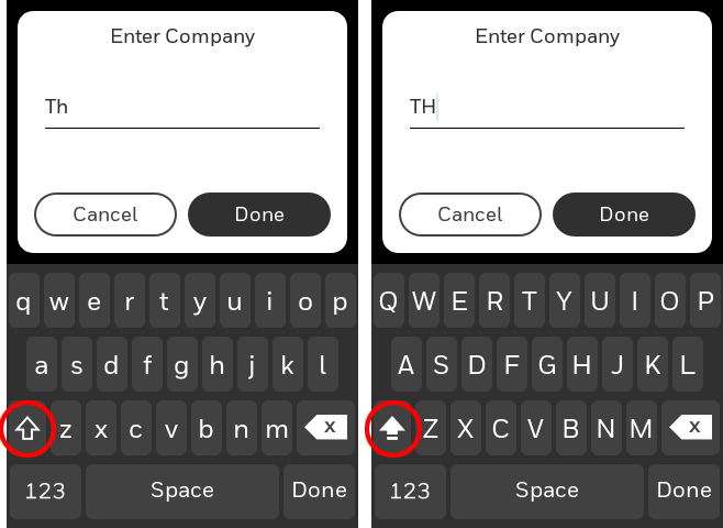
Caps Lock
When entering contractor information, customer Dry Contact Alert message, etc., double-click the Shift key to enter text all in upper-case:
Auto Changeover Operation
Auto changeover is available if the thermostat is configured for at least 1 Heat stage and 1 Cool stage and ISU 3000 is set to “Auto”.
When configured this way, you can select “Auto” as one of the options under “System mode”.
ISU 3015 is the auto changeover differential setting. It can be set from 0-3 °F (0-2.5 °C). When in auto mode, the customer can always set the Heat and Cool setpoint to the same temperature, regardless of the differential setting although most customer prefer to have a cool setpoint that is at least 3 degrees above the Heat setpoint. When 0 is selected, we enforce a 1.5°F differential behind the scenes to ensure the heat doesn’t come on after cooling shuts off or vice-versa.
The differential is the minimum number of degrees the temperature needs to rise or fall before switching from Heat to Cool while in auto changeover mode. Example: With a differential of 3, if heat and cool were both set for 70, and heat had been used last, the temperature would need to rise at least 3 degrees above the heat setpoint before the thermostat would turn on cooling. Then it would run cooling down to setpoint and cycle cooling on and off to maintain setpoint. The temperature would then need to drop at least 3 degrees below the cool setpoint before heat could come on.
If the AC is used for dehumidification then we enforce an additional temp drop below the over-cooling amount, (ISU 9070) prior to switching back to heat.
Em Heat and Auxiliary Heat Operation
Auxiliary Heat:
Auxiliary Heat runs as backup to the heat pump. It runs with the heat pump when:
-
The thermostat is set to Heat mode.
-
The Backup Heat is set to electric (ISU 2180).
-
Load conditions determine Backup Heat is needed.
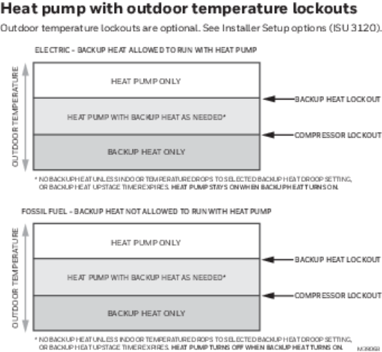
The heat pump could be locked out when in Heat mode by the balance point setting (ISU 3120) or if the backup heat is gas or oil and backup heat differential (ISU 3090) or upstage timer (ISU 3110) are used.
Emergency Heat:
Emergency Heat runs when you manually switch the thermostat to the Em Heat mode. When the thermostat is in Emergency Heat mode, the heat pump is locked out.
Emergency Heat mode is only available when the thermostat is configured for a heat pump (ISU 2000) and Backup Heat stages is set to 1 (ISU 2071).
From the home screen touch the menu icon and then “System Mode”. You can set the thermostat to Heat, Off, Cool, Emergency Heat, or Auto. (Auto only available if ISU 3000 is set to Auto.)
When the thermostat is set to Em Heat mode, the heat pump is locked out and the Backup Heat is used to maintain the heat setpoint.
If ISU 2175 is set to “Drive aux and E together”, then with a call for emergency heat or auxiliary heat, both E and AUX terminals are energized. Typically the backup heat is wired to Aux and E is unused when set this way.
If ISU 2175 is set to “Aux and E independent”, then with a call for emergency heat, the E terminal is energized and the Aux terminal is not. The wire to Aux controls a heat source that runs as backup heat to the heat pump when the mode is set to “Heat”. The wire to E controls a heat source that runs independent of the heat pump when mode is set to Em Heat. In most cases, the heat pump uses the same heat source for auxiliary heat and em heat.
Dual fuel systems (Heat pump with gas or oil furnace backup) cannot run the heat pump and furnace at the same time.
Adaptive Intelligent Recovery
Over time, the T10 or T10+ thermostat learns how long it takes your system to reach your programmed temperature setting.
The thermostat turns on the heating/cooling system early and assures that the programmed temperature setting is reached at the programmed time regardless of weather conditions. For example, if the Wake program period is set to 6:00 am with a heat setting of 70 degrees, the heat will turn on before 6:00 am, so the temperature is 70 degrees at 6:00 am. The thermostat displays “In Recovery” when it turns the system on early.
Adaptive Intelligent Recovery® calculates the recovery ramp based on how far the room temperature is away from the temperature setting, previous equipment performance and weather history, allowing the thermostat to start recovery at the optimal time so it can reach the programmed temperature setting at the programmed time. The T10 or T10+ thermostat uses two recovery ramps when set up to control a heat pump system; one ramp for the compressor and one ramp for the auxiliary heat. Once the room temperature intersects the compressor ramp, the compressor turns on until the setpoint is reached. If the room temperature does not rise quickly enough and intersects the second ramp, the auxiliary heat turns on. It takes about one week for the thermostat to adjust to weather conditions, equipment performance and construction of the home. If the temperature setting is reached too early or too late, the ramp is adjusted for the next day's recovery. See figure below:

Compressor Protection
The thermostat keeps the compressor off for a few minutes before restarting, to prevent equipment damage. During this “off” time, the message "Waiting for equipment" is displayed on screen.
P + I Control
A conventional mechanical or electronic thermostat does not control temperature precisely at setpoint. Typically there is an offset (Differential) in the control point as the system load changes. Many factors contribute to offset including the switch differential, thermal lag, overshoot, cycle rates and system load.
The T10 or T10+ thermostat however, works much differently than a conventional mechanical or electronic thermostat when Differential is set to comfort. Differential is always set to comfort and not adjustable when controlling a 2 stage furnace or 2 stage heat pump without Aux Heat. The proprietary algorithm in the thermostat eliminates the factors causing offset (Differential). This makes temperature control more accurate than the conventional mechanical or electronic thermostat. The temperature control algorithm is called proportional plus integral (P + I) control.
The thermostat sensor or indoor sensor senses the current space temperature. The proportional error is calculated by comparing the sensed temperature to the setpoint temperature. The deviation from the setpoint is the proportional error.
The thermostat also determines integral error, which is a deviation based on the length of error time (how long the sensed room temperature has been away from the setpoint temperature). The sum of the two errors is the (P + I) error.
The cycle rate used to reach and maintain the setpoint temperature is computed using the P + I control algorithm. The addition of the integral error is what differentiates the thermostat from many other mechanical and electronic thermostats.
Heat Differential
For stage 2 of conventional systems or 2 stage heat pump without Aux Heat
The thermostat will use the stage of heating as needed to keep the indoor temperature within 1 °F (0.5 °C) degree of the setpoint. The thermostat turns on stage 2 when the capacity on stage 1 reaches 90%.
Heat pumps with electric Aux Heat when Differential is set to “Comfort”
The thermostat will use the stage of heating as needed to keep the indoor temperature within 1 °F (0.5 °C) degree of the setpoint. The thermostat turns on Aux Heat when the capacity on highest compressor stage has reaches 90%.
Heat pumps with electric Aux Heat when Differential is set to 2°F or higher(2 °F to 15 °F adjustable)
If the indoor temperature drops to the Differential amount while the highest compressor stage is running the thermostat will continue to run the heat pump stages and also energize the Aux Heat.
For example, if the Backup Heat Differential is set to 2 °F (1.0 °C), the indoor temperature must be 2 °F (1.0 °C) below the setpoint before the backup heat turns on. When a manual temperature change is made, there will typically be a delay before the thermostat brings on the backup heat, regardless of the upstage timer settings. When Differential is set to other than Comfort, the upstage timer and Holdoff timer settings are also available.
Dual Fuel heat pumps with gas or oil Backup Heat
If the thermostat is configured to control dual fuel, the Differential cannot be set to Comfort. It will default to 2 °F and can be adjusted from 2 °F to 15 °F.
If the indoor temperature drops to the Differential amount while the highest compressor stage is running the thermostat will end the call for the heat pump stages and run the fossil fuel heat stage.
For example, if the Backup Heat Differential is set to 2 °F (1.0 °C), the indoor temperature must be 2 °F (1.0 °C) below the setpoint before the thermostat will shut down the heat pump and run the fossil fuel heat.
When a manual temperature change is made, there will typically be a delay before the thermostat brings on the Backup Heat, regardless of the upstage timer settings.
Upstage Timer
The Upstage timer setting is only available when:
-
The thermostat is configured for a heat pump with an aux heat stage (electric of fossil fuel).
-
The Differential setting is set to a setting other than “Comfort” (2 °F to 15 °F).
Backup Heat Upstage Timer options are Off, 30 minutes to 16 hours. Default is Off.
The upstage timer allows* the Aux Heat to run when the highest heat pump stage has run for longer than the timer setting during a steady state condition. Steady state means the thermostat is cycling to maintain setpoint.
Manually raising the setpoint or a scheduled setpoint change will not trigger the upstage timer. In those conditions the thermostat will not use Backup Heat unless a different condition triggers the thermostat to run the Backup Heat (Differential, balance point, or manually switching the thermostat to Em Heat mode).
*Differential and upstage timer are designed to restrict the auxiliary heat for customers who are energy conscious. The aux heat does not necessarily run after the timer has expired even in a steady state condition. Once the timer expires in steady state the thermostat calculates whether or not to run the aux heat based on the load capacity of the highest heat pump stage.
If the heat pump struggles to maintain setpoint, we would suggest one of the following steps:
-
Verify the heat pump is operating as expected.
-
Set a balance point. If a balance point is already used but the heat pump cannot handle the load even when operating correctly, the installer may need to raise this setting.
-
For heat pump with electric backup heat, set the Differential to “Comfort”, this uses the backup heat more aggressively.
Holdoff Timer
The Backup Heat Holdoff Timer is available for any system with 2 heating types, the Backup Heat Differential is set to 2 °F (1.0 °C) or higher, and backup heat upstage timer is set to 30 minutes or more. Unlike the upstage timer, the holdoff timer can be activated by a temperature set point change (not limited to steady state). The holdoff timer starts when the highest stage of the previous equipment type turns on. The out-of-box setting is “Auto” and the thermostat will hold off the use of backup heat as long as possible when the set point is changed. If this is changed to a setting other than Auto, then the auxiliary heat will be FORCED to turn on after this time is met.
Programmed Recovery
If the primary heat is making progress as expected, backup heat will not be used to reach the setpoint of the next program period. Backup heat is always restricted during a programmed recovery when the Adaptive Intelligent Recovery feature is used. See note below.
NOTE: During a programmed recovery (or when the temperature setpoint is changed by the user), the thermostat waits to turn on the backup heat depending on system performance, load conditions and how many degrees the temperature setpoint is changed. Backup heat will be used ONLY when the temperature is not rising quickly enough to reach the setpoint in a reasonable time. Upstage timer for heat pump with aux heat applications is only used in steady state (cycling to maintain setpoint). The thermostat will not run the aux heat during a programmed recovery unless one of the following conditions occurs:
-
Differential is set for comfort and thermostat calculates that the heat pump cannot effectively handle the load conditions.
-
Differential is set to 2 °F to 15 °F and indoor temperature drops while the highest stage of heat pump is running.
-
Outdoor temperature drops below the balance point setting (if used).
-
Thermostat is manually switched to em heat mode.
Finish with High Heat stage and/or Finish with High Cool stage
These settings allow the installer to keep the high stage of the equipment running until the desired setpoint is reached. This setting is recommended for Geothermal Heat Pumps to allow the loop to rest.
When set to no (default), the thermostat cycles the stages based on load conditions and the cycle rate setting for these stages.
“Finish with High Cool Stage” is ISU 3020.
“Finish with High Heat Stage” is ISU 3021.
Set to Yes to turn on these features. The default is No.
Heat Pump and Backup Heat Lockout Operation
Fan Coil Unit Settings and Operation
Fan Coil Unit Settings
T10+ thermostats with the latest firmware can be configured to control a 2-pipe fan coil or a 4-pipe fan coil. Prior to that, T10 & T10+ models could support a hot water fan coil (used for heat only).
Hot water fan coil - (Supported by all models of T10 & T10+) A hot water fan coil requires that the thermostat energize W to move hot water through a coil that is inside the HVAC supply ducting and then turn on the blower fan to blow air over the hot coil and deliver it to the space. All T10 & T10+ thermostats have a setting for this. The T10 or T10+ energizes a single blower speed, wired to G for these systems.
4-pipe fan coil - (Supported by T10+ with firmware 03.03.08.02 or later and EIM [if used] with firmware 01.02.01.00 or later) A 4-pipe fan coil requires that the thermostat energize W to move hot water through a hot water coil or energize Y to move cold water through a cold water coil. Then the thermostat turns on the blower fan to blow air over the hot coil and deliver it to the space. Most 4-pipe fan coil units have multiple fan speeds. The low speed fan is wired to G. The medium speed fan is wired to Y2. The high speed fan (if used) is wired to U. There are other special fan coil unit settings which can vary for different systems. These settings are covered in the Fan Coil Unit section.
2-pipe fan coil - (Supported by T10+ with firmware 03.03.08.02 or later and EIM [if used] with firmware 01.02.01.00 or later) A 2-pipe fan coil energizes the same terminal (Y) to move hot water through a coil as it does to move cold water through a coil. Therefore, a thermostat that controls a 2-pipe fan coil needs to know whether the pipe is hot or cold. When it senses that the pipe is hot, the T10+ automatically switches to heat mode. When it senses that the pipe is cold, the T10+ automatically switches to cool mode. If there is an emergency heat stage, the user can manually switch the thermostat to emergency heat mode when the pipe temperature is below the heat threshold setting. In that case, the T10+ energizes the Aux to run the backup heat.
The T10+ has different options for how to perform the changeover from heat to cool based on pipe temperature.
-
The T10+ can be used with a 10K or 20K sensor
-
The T10+ can be used with a dry contact switch (such as an aquastat) to switch from heat mode to cool mode based on pipe temperature. The wiring diagrams for the fan coil unit section show how to wire the dry contact switch or wired sensor for this purpose. The ISU section shows the configuration settings.
When running heat or cooling, the T10+ turns on the blower fan to blow air over the coil and deliver the conditioned air to the space. Most 2-pipe fan coil units have multiple fan speeds. The low speed fan is wired to G. The medium speed fan is wired to Y2. The high speed fan (if used) is wired to U.There are other special fan coil unit settings which can vary for different systems. These settings are covered in the Fan Coil Unit section.
Fan Sequence Operations
(ISU 2105, 2106, 2107)
ISUs 2105 – 2107 are used to select the number of fan speeds controlled on a fan coil unit system and assign (or be instructed) where these speeds are wired to.
(ISU 3320)
ISU 3320 allows the installer to select how the fan speed is controlled when the T10+ is controlling a fan coil unit with multiple fan speeds. The options are Auto, Multiple Speeds, or All Allowed. When ISU 3320 is set for Auto, the T10+ uses the fan ramping algorithm to control the fan speed with a call for heat or cooling. The fan will be off with no call for heat or cooling. If ISU 3320 is set to Multiple Speeds, the user may select Lo, Med, or Hi from the fan menu. The thermostat will continuously run at the speed selected. If ISU 3320 is set to All Allowed, the user may select Auto, Lo, Med, or Hi from the fan menu. When Auto is selected, the fan runs only during heat or cool calls and the fan speed at which it runs is based on the control algorithm. If set to Lo, Med, or Hi, it will continuously run at the speed selected both in Idle and with a call for Heat or Cool.
(ISU 3325)
ISU 3325 allows the installer to select whether the fan always starts at the highest speed when there is a call for Heat or Cool. Some systems require this to ensure that the fan starts correctly. If enabled, the fan will start at the highest speed. If set to a speed other than High, the thermostat will then reduce the fan speed to the one selected in the fan settings or control to the correct speed based on the control algorithm if it is set to AUTO.
(ISU 3340)
ISU 3340 allows the installer to select whether the fan will reset to the Auto mode after a time delay when the user makes the setting Lo, Med, or Hi. The options are Off, 2 hours or 4 hours. If set to Off, the T10+ will run at the fan speed selected by the user indefinitely until the fan speed is changed manually.
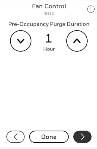
(ISU 4010)
ISU 4010 allows the installer to determine if a pre-occupancy purge is used. This option applies to any light commercial application that has a fan and is using a schedule. This setting determines if the fan should run prior to the Occupied schedule, and if so how far in advance. If a system with multiple fan speeds is used, this option will run the fan at the highest speed during this time.
Remote Setback (Occupancy Sensing)
The T10+ thermostat allows you to use Remote Setback (sometimes referred to as Occupancy sensing or Occupancy setback). This energy-saving feature can be enabled using one or more C7189R3002 wireless indoor sensors, or with an occupancy sensor that opens or closes a dry-contact switch.
During occupied or away schedule periods, the sensor tells the thermostat to switch to STANDBY (Setback settings) when no one is detected in the space(s) where the sensors are located. During that time, the display shows "STANDBY SETPOINTS ACTIVE" in the display. If a person is detected by the sensor(s), the thermostat follows the settings of the Occupied (Home) schedule period. The occupancy sensor(s) are ignored during unoccupied / Away schedule periods. When occupancy is detected, the thermostat follows the schedule settings or a manual override setting.
To use the feature for energy savings when a room is unoccupied, but no regular Occupied schedule has been set:
The installer can access the Schedule menu and disable any scheduled period except Occupied 1 (Commercial) or Wake (Residential). In this way, the thermostat will have an Occupied schedule setting to which it can default when occupancy is detected.
Setup:
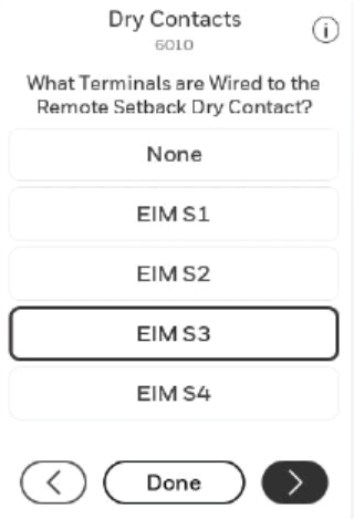
ISU settings 2240, 6000, 6010, 6020, 6030 & 6040 are related to Remote Setback/Occupancy Sensing. ISU 6000 and 6010 & 6020 are only used when a remote setback switch is used (rather than wirelsss sensors), depending on what triggers occupancy sensing. If an occupancy sensor opens or closes a switch when occupancy is detected, that switch is wired to R at HVAC and L at T10+ when an EIM is not used. If an EIM is used, the switch is wired to S1, S2, S3, or S4 terminals. See the wiring diagrams below in this section.
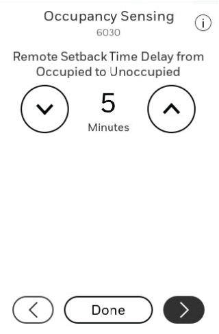
A Remote Setback Time Delay (ISU 6030) can be set to force the thermostat to wait before it switches from occupied settings to the standby settings. This allows the room to stay comfortable if the room is unoccupied for a short period of time. When set to 0 minutes, the thermostat will switch from occupied settings to the standby settings immediately when the room is unoccupied.
This feature is most commonly used in commercial buildings but some energy-conscious homeowners also use this in residential applications. To best balance comfort and efficiency, it is recommended to have enough sensors to cover all spaces that are heated or cooled by the thermostat.
Hotel Card Reader:
Some Fan Coil Unit thermostats used in hotels use a remote setback triggered by a room key card holder. If the guest inserts the key card into the holder while in the room, the thermostat will switch to Occupied temperature settings. When using an EIM, the wires from the card reader go to the S contacts on the EIM, (the same as on a TB7100 thermostat). If the EIM is not used, one of these wires goes to R at HVAC and the other wire goes to L at thermostat/UWP. See the wiring diagrams.
Set Up Remote Setback / Occupancy Sensing
-
Select a remote setback option in ISU 2240 (see Figure below). C7189R3002 wireless indoor sensors have a built-in motion sensor. The “Dry Contact” or “L Terminal” settings require an external occupancy sensor which opens or closes a switch when occupancy is detected.
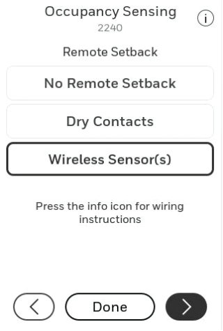
Options when EIM is used.
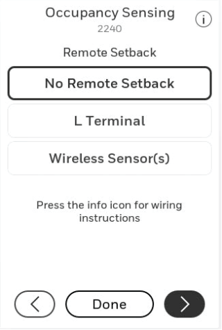
Options when EIM is not used.
-
If a dry contact is used to initiate Remote Setback and an EIM is used, 6010 is used to assign the Occupancy Sensor to a set of S contacts on the EIM.
-
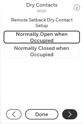
The setting below is shown if either Dry Contacts or L Terminal is selected for 2240. Select Normally Open when Occupied or Normally Closed when Occupied, based on the type of dry contact device installed.
-
Normally Open when Occupied: The Dry Contact device is open when the room is occupied and will close when the room is unoccupied.
-
Normally Closed when Occupied: The Dry Contact device is closed when the room is occupied and will open when the room is unoccupied.
NOTES:
-
ISU 6030 is shown unless No Remote Setback is selected for ISU 2240. Select a Remote SetbackTime Delay (See Figure below). The Remote Setback Time Delay forces the thermostat to wait before switching from Occupied settings to the Standby settings. When set to 0 minutes, the thermostat will switch from settings to the Standby settings immediately when the room is unoccupied.
-
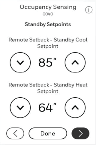
Select the Standby settings that you wish to maintain when the occupancy sensor detects that the room is unoccupied.

Remote Setback using a Dry contact switch on a T10 with EIM

Remote Setback using a Dry contact switch on a T10+ Without EIM
Hotel Card Reader retrofit
If wires going to S and S on a previous thermostat went to a card reader or other dry-contact occupancy sensor, they can be wired to the T10+ thermostat or EIM as shown in the diagrams below.
A 10K/20K cannotbe wired to L or R as shown below. A 10K/20K sensor wires to a set of S terminals at either EIM or T10+/UWP.
In retrofit installations: If T10+ is used without EIM, you can pig-tail one of the existing wires to R at the thermostat. Polarity does not matter when re-wiring to R and L at UWP. Then follow the following ISU settings.
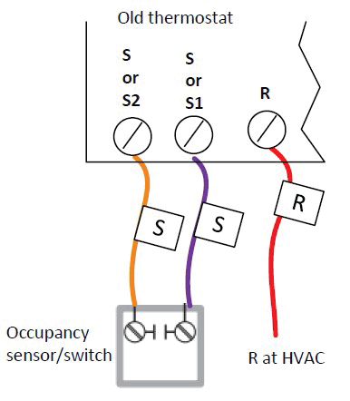
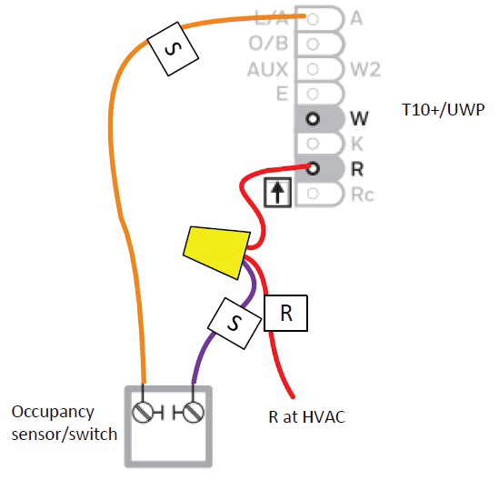
NOTE: These wiring diagrams do not show the rest of the system wiring, which will vary. SeeWiring at T10 or T10+ without EIM for system wiring not shown here.
Dry Contact Alerts (ISU 6000- 6220)
A Dry Contact device such as a wet switch can be connected to the S1, S2, S3, or S4 terminals at the Equipment Interface Module. When the dry contact device detects a problem, the thermostat displays an alert on the home screen along with the dealer information.
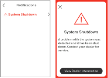
When the user presses the alert for more info, the Notification screen is displayed, prompting them to contact their dealer.
The following Dry Contact Alerts are available for the T10+ with EIM:
Full Drain Pan Alert
When the dry contact device detects that the condensate drain pan is full, the thermostat provides an alert to the user.
NOTE: When a Full Drain Pan Alert is selected, there is a follow up setting asking if you want to shut off the system when this alert is active or just send the alert message.
Dirty Filter Alert
When the dry contact device detects a dirty air filter (pressure drop across the filter), the thermostat provides an alert to the user to replace the filter.
Water Leak Alert
When the dry contact device detects a water leak, the thermostat provides an alert to the user.
NOTE: When a full Water Leak Alert is selected, and the T10+ is configured to control a humidifier there is a follow up setting asking if you want to shut off the humidifier when this alert is active or just send the alert message.
System Shutdown Alert
When the dry contact device detects a critical problem with the system, the thermostat alerts the user that the system was shut down. When the dry contact device detects a problem with the system (for example, smoke detection), the thermostat will not call for heating, cooling, fan or IAQ equipment until the dry contact is deactivated or the feature is no longer configured at the thermostat.
Service Needed Alert
When the dry contact device detects an issue that requires service, the thermostat provides an alert to the user.
Fan Failure Alert
The Fan Failure Alert protects the equipment when there is no airflow. When the dry contact device (for example, sail switch) detects no airflow for 5 minutes after a call for forced air heat, cool or fan, the thermostat alerts the user that the system was shut down due to a lack of airflow. The thermostat will call for the fan and lock out all other equipment until the dry contact device senses air flow again or the feature is no longer configured at the thermostat.
Custom Alert
Allows the dealer to enter a custom alert to be displayed when a dry contact device is activated. For example, a float switch can detect when your sump pump is not working.
Dry Contact Setup Example
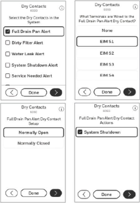
Dry Contact setup example
Custom Alerts 1 through 4
Allows the dealer to enter a custom alert to be displayed when a dry contact device is activated. For example, a float switch can detect when your sump pump is not working.
When Custom Alert 1 through Custom Alert 4 is selected in ISU 6005, the T10+ asks you to name the alert and then gives options for additional settings related to the alert. These settings are:
-
Which set of S terminals on the EIM the Dry Contact Alert is wired to (ISU 6190).
-
There are four (4) sets of configurable S terminals on the EIM. If a set of S terminals is already configured for use by a different Dry Contact Alert (or sensor), it will not be configurable.
-
Whether the switch wired to these terminals is normally open or closed (ISU 6200).
-
The switch wired to the S terminals could either be open in normal (not alert) conditions or closed.
-
Enter the Dry Contact Alert name (ISU 6210).
-
Whether there is an alert message displayed when the alert is active (ISU 6215).
-
In most cases, the installer would want an alert message to appear on the T10+ if there was a Dry Contact Alert active. However, the installer may be using the “alert” to do some other action (like running a ventilator when a sensor is reading high CO2). This may be normal operation and they may not wish to show an alert.
-
Lock Out Heat or Lock Out Cool (ISU 6230)
-
If the installer chose to lock out heat or cool on a custom Dry Contact Alert condition, the T10+ will then ask if: "You want a delay before the lockout (ISU 6600 or 6620). For example, if someone was using a door sensor to lock out cooling, you wouldn’t want to short cycle the cooling every time someone enters or exits. But if the door is left open for a certain length of time, you may wish to shut down the heat or cooling." Or, "If you still want a maximum temperature for cool (ISU 6610) or minimum indoor temperature for heat (ISU 6630). Example: If someone had a heat lockout configured when the window was open, they left the window open, and the indoor temperature dropped to 40°F, you probably still want the heat to run because the danger of pipes freezing overrides the inefficient use of heating with a window open"
-
Activate Fan (ISU 6230)
-
If selected, this setting turns on the fan when the selected custom Dry Contact Alert (custom dry contact 1 through 4) is active.
-
Activate Custom U terminal (ISUs 6230, 6240, 6250, 6260)
-
If you choose to activate a custom U terminal during a custom alert, the T10+ will ask you to name the U terminals used. That way the T10+ equipment status menu can show what is being turned on or locked out. For example, you could wire a shut off valve to the U contacts and the status would then show “Shut off valve energized” under equipment status.
-
Humidifier Lockout (ISU 8095)
-
If the T10+ and EIM are set for a custom Dry Contact Alert and to control a humidifier, you can choose to lock out the humidifier during a custom Dry Contact Alert (the Water Leak Alert option also offers this setting).
-
Dehumidifier Lockout (ISU 9145)
-
If the T10+ and EIM are set for a custom Dry Contact Alert and to control a dehumidifier, you can choose to lock out the dehumidifier during a custom Dry Contact Alert.
-
Turn On Ventilator (ISU 10065)
-
If the T10+ and EIM are set for a custom Dry Contact Alert and to control a ventilator, you can choose to turn on the ventilator during a custom Dry Contact Alert.
-
Lockout Ventilator (ISU 10140)
-
If the T10+ and EIM are set for a custom Dry Contact Alert and to control a ventilator, you can choose to lock out the ventilator during a custom Dry Contact Alert.
Battery Replacement
Indoor Sensor
Replace batteries in your indoor sensor when a warning appears on the thermostat screen, about 60 days before batteries are depleted.
When the sensor status light begins flashing red, battery power is critically low and will be depleted within 2–3 weeks. During normal operation, the status light remains off.
To replace the batteries:
-
Remove the sensor from wallplate.
-
Install 2 fresh AAA alkaline batteries. If the status light flashes green, batteries are good; if it flashes red, you must use fresh batteries.
-
Attach sensor to wallplate.
The sensor will restore communication with the thermostat a few seconds after new batteries are installed.
Outdoor Sensor
Replace batteries in your outdoor sensor when a warning appears on the thermostat screen, about two months before batteries are depleted.
After new batteries are installed, the outdoor sensor will restore communication with the wireless network within a few seconds.

Outdoor sensor battery installation
Commercial Features
The thermostat can be set up for residential or light commercial applications (ISU 1010). When the thermostat is set up for Commercial, the thermostat meets Commercial Code, Title 24 and provides the following features:
-
Commercial language (Occupied and Unoccupied)
-
Temporary override (permanent hold is not allowed)
-
Temporary override duration is limited to the amount set by the installer
-
Adjustable ramp rates
-
Initiate occupancy
-
Displays name on home screen
-
Remote setback using an occupancy sensor
-
Economizer or Time of Day output
-
Pre-occupancy purge
-
Additional dehumidification control options

Select Residential or Commercial
Overriding Schedules:
Commercial Use
Touch 5or 6 to adjust the temperature. It will be maintained until the hold time you set.
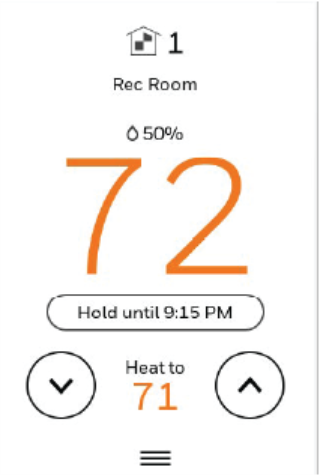
-
To change the hold time, touch Hold Until. Then use the arrow buttons to change hold time. This time can be adjusted up to the maximum time set by the installer.
-
Touch Override to use a pre-set occupied temperature if a person uses the room during an unoccupied period. The new temperature will be maintained for 1 hour and can be adjusted up to the maximum time set by the installer.
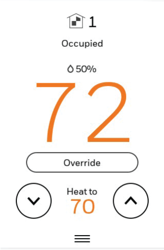
The programmed schedule will resume when the override timer expires. Touch Cancel Hold at any time to resume the program schedule.
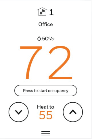
Initiating Occupancy Mode: Commercial Use
This feature keeps temperature at an energy-saving level after the thermostat transitions from an Unoccupied schedule period to an Occupied schedule period until someone touches Press to start occupancy. When you arrive, touch the button to maintain a comfortable temperature while the room is occupied. This feature might be used in a school room that isn’t occupied every day.
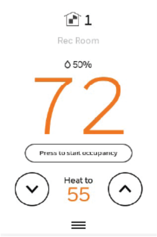
Touch the 5or 6buttons to set the temperature or the Hold Until time. The temperature is maintained until the time you set. Temperature returns to an energy saving level after the timer expires, or the Occupied period ends.
This feature is available only when programmed by the installer in ISU 4020 & 4030.
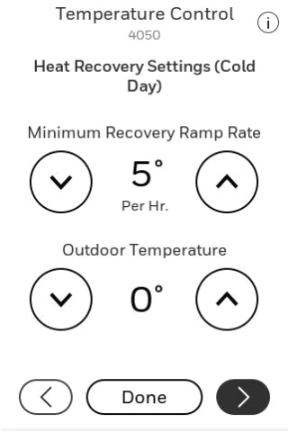
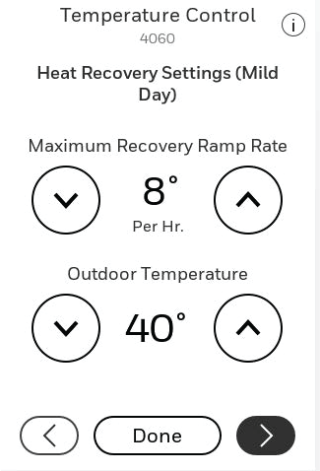
Ramp Rates
When the ramp rate is set to Off, the thermostat begins recovery at the scheduled time.
When a ramp rate is set, recovery begins early to reach the setpoint by the program time. Based on your recovery ramp setting and how far the thermostat is set back, the thermostat determines how early to turn on the system.
If the T10+ is set to use a wired sensor, wireless sensor, or Internet for outdoor temperature (ISU 1060), you can set outdoor temperatures for mild, cold and hot days in your region. By setting these outdoor temperatures, the thermostat will automatically adjust the ramp rate based on outdoor conditions. This allows the thermostat to save energy by starting recovery at the optimum time as outdoor conditions change.
NOTE: The thermostat uses an adjustable ramp rate when the thermostat is set up for Commercial. This allows the thermostat to recover on time during changing conditions (occupancy changes, temperature overrides, load conditions, opening/closing of doors, etc.) which are common in commercial applications.
Custom Names
The thermostat location (name) can be displayed on the home screen. See the name “OFFICE". This is useful when multiple thermostats are mounted in a manager’s office or equipment room, to quickly identify which thermostat controls a specific zone or area.
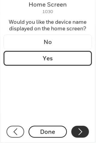
When configured for Commercial application, the T10+ will ask you to select the room where it is installed during initial setup. If you select Yes for ISU 1030, this is the name that will be displayed on the home screen. To change the name after setup is complete, go to Installer Options > Devices and Sensors-Thermostat. Then select Change Room. You may choose a pre-selected room name or choose Other-Add-Room to enter a custom name.
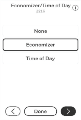
Economizer and Time of Day (TOD) Operation
Economizer
The T10+ thermostat controls an Economizer module to provide ventilation during occupied periods and free cooling when outdoor conditions are favorable. In some climates the cooling system may run several hours when it may not be required to maintain indoor comfort. When outdoor conditions are favorable, ventilation with outdoor air can achieve the same level of comfort at lower cost. Advanced Features explains how the Economizer Module is controlled by the thermostat.
The T10+ thermostat works with the Jade W7212 Economizer Module for conventional systems and the Jade W7213 and W7214 Economizer Modules for heat pump systems.
|
Thermostat Mode |
Equipment Operation |
U Contacts |
|
Occupied |
Heat/Cool running * |
Closed |
|
Occupied temporarily |
Heat/Cool running * |
|
|
Occupied |
Heat/Cool NOT running * |
|
|
Occupied temporarily |
Heat/Cool NOT running * |
|
|
Pre-occupancy purge |
Fan running |
|
|
Unoccupied |
Cooling system running |
|
|
Unoccupied temporarily |
Cooling system running |
|
|
Standby |
Cooling system running |
|
|
Unoccupied |
Cooling system NOT running |
Open |
|
Unoccupied temporarily |
Cooling system NOT running |
|
|
Standby |
Cooling system NOT running |
Closed |
|
Non-programmable |
Fan running |
|
|
Non-programmable |
Fan NOT running |
Open |
* Fan (G) always energized during Occupied & Occupied Temporary modes.
Time of Day (TOD)
The T10+ thermostat can be set up for a Time of Day output in the installer setup. This output is commonly used to control lighting panels, turning them on for occupied periods and off for unoccupied periods. The TOD Table explains how the TOD feature works with various thermostat modes.
|
Thermostat Mode |
U Contacts |
|
Occupied |
Closed |
|
Occupied temporarily |
|
|
Temperature overrides |
|
|
Unoccupied |
Open |
|
Unoccupied temporarily |
|
|
Standby |
|
|
Non-programmable |
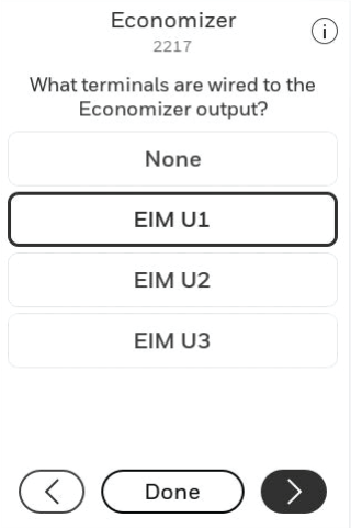
The Economizer Module and Time of Day output connect to the U terminal at the thermostat or EIM and are set up at ISU 2216-2220.
Pre-Occupancy Purge
The T10+ thermostat can be set up for Pre-Occupancy Purge in the installer setup (ISU 4010). When setup for Pre-Occupancy Purge, the thermostat runs the fan 1 to 3 hours before each occupied period to provide a comfortable workplace upon arrival. Options are Off and 1 to 3 hours.

Economizer control using T10+ thermostat without EIM
NOTES:
-
U Slider tab must be in up position on UWP.
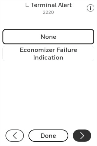
- L/A only used if economizer fault indication is needed on T10+

Economizer control using T10+ thermostat with EIM
NOTES:
- Any set of U contacts can be used (selected in ISU 2217). Jump the unused U from the selected set to R on the EIM as shown.
- L only used if Economizer fault indication is needed on T10+